REPAIR SHOP
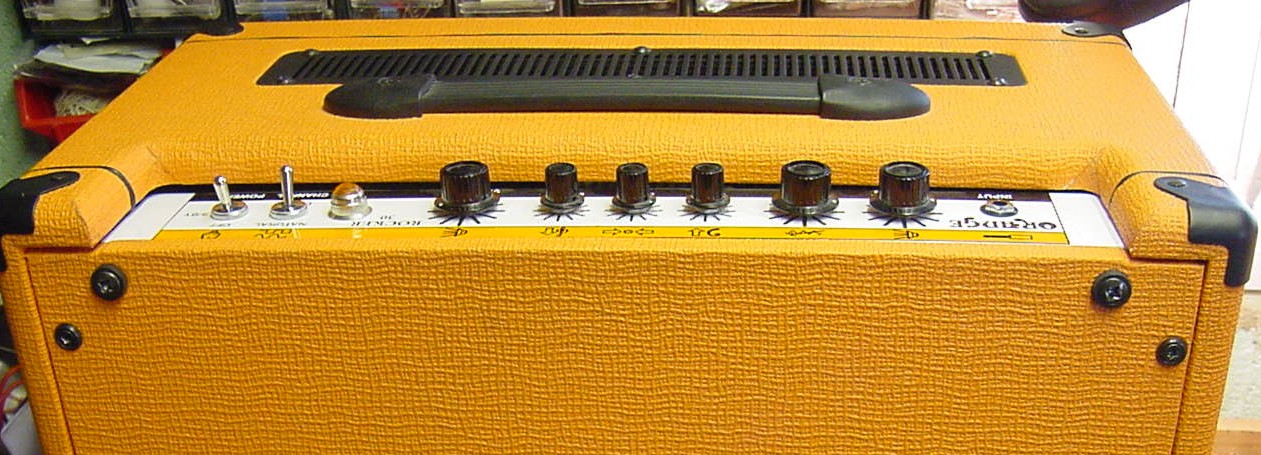
Repair of Orange Rocker 30 Valve Guitar Amplifier
For a very nice chap Lars Mullen http://www.larsmullen.co.uk/
Music
Media Announcements
Tel: +44 (0)1803 523794
Mobile: 07923573759
Email: info@larsmullen.co.uk
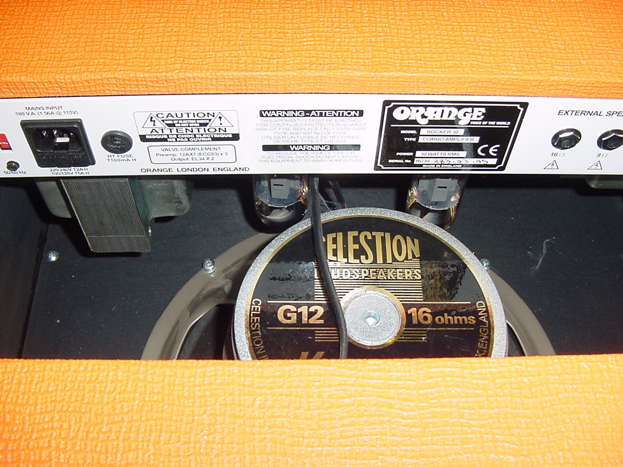
Fault - The amplifier keeps blowing the 500mA HT Fuse

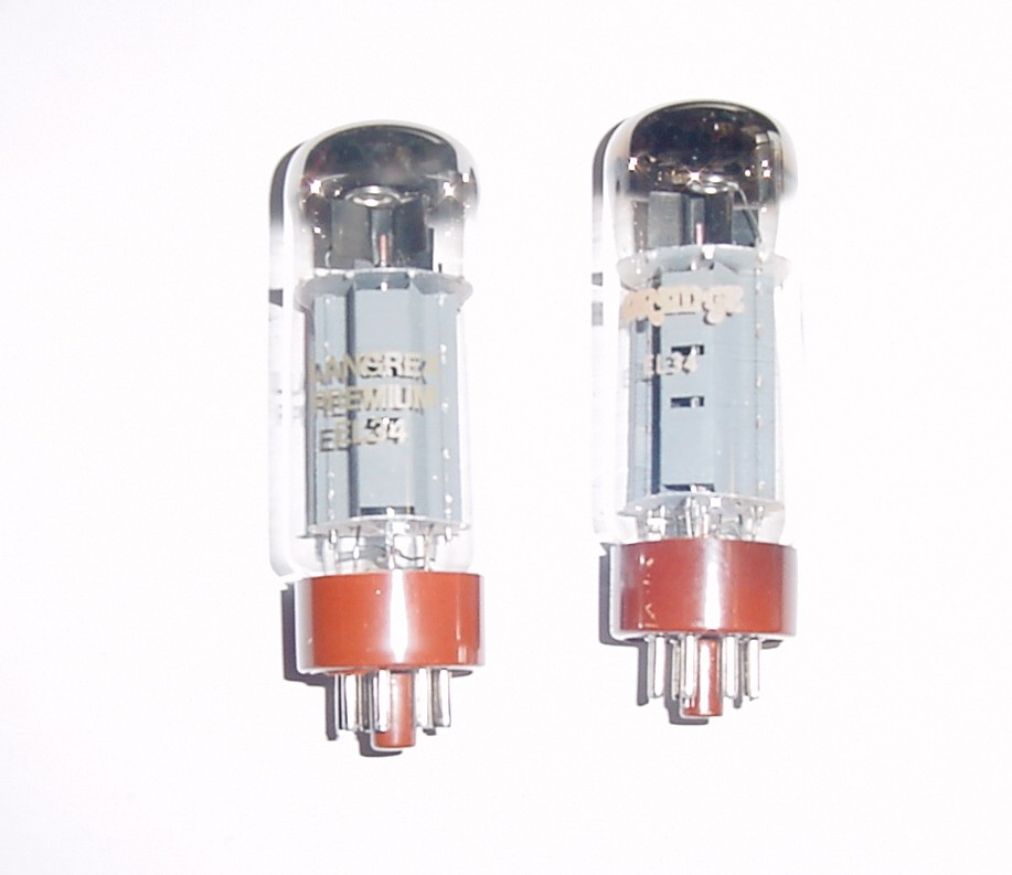
Removed the EL34 Output valves replaced the HT fuse, this fuse did not blow - leading me to the conclusion that one of the EL34s was faulty
emailed Orange to get the schematic as I needed to check a few of the voltages in the amplifier to satisfy myself that all was well , although the amplifier itself is quite simple I have not necessarily got time to strip the amplifier down to trace things through and make my own schematic, it is far easer to have the diagram, unfortunately was not able to obtain the schematic from orange
Removed the amplifier chassis, removed old output valves and installed new ones
See bellow a comparison of new and old, we chose some reasonable replacements from a trusted supplier LANGREX, a matched pair of EL34s - as you can see they probably came from the same factory in China as they seem identical except for the screen printing on the glass.
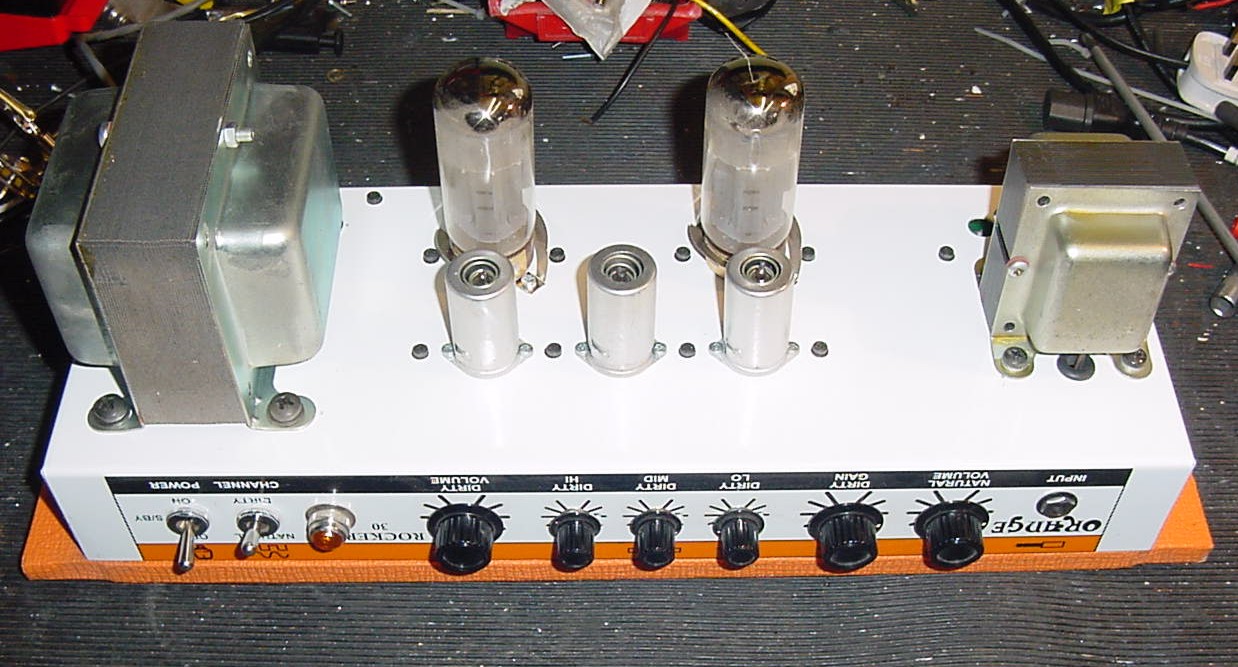
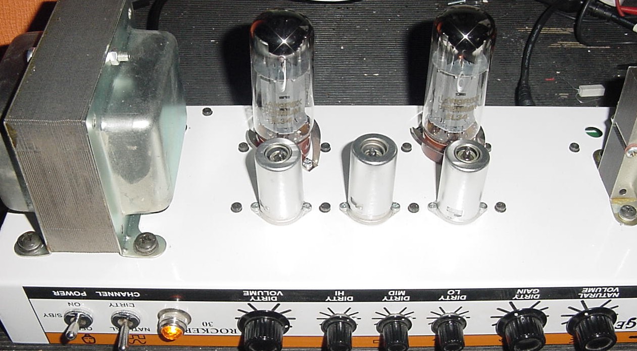
See bellow the full complement of valves
Back row EL34 EL34
Front Row left to right E83CC ECC83 E83CC
Yes you are reading the correctly the lower left and right hand valves are indeed E83CC these are special quality ECC83 although what the special qualities are remains a mystery, E83CC probably has lower microphonics and noise than a regular ECC83,
On checking various voltages did not seem to get the readings I was expecting, so I had to bite the bullet and strip the amplifier down for further investigation, see bellow the underside of the chassis disconnected the PSU transformer to test the various voltages
As Follows
TX1 PURPLE TX3 PURPLE 533V HT ALSO TX2 TX5 WHITE AND GREY TO 0V GIVING 2 X 266V
TX6 YELLOW TX4 YELLOW 6.27V HEATER
TX7 RED TX8 BLACK 4.79V HEATER
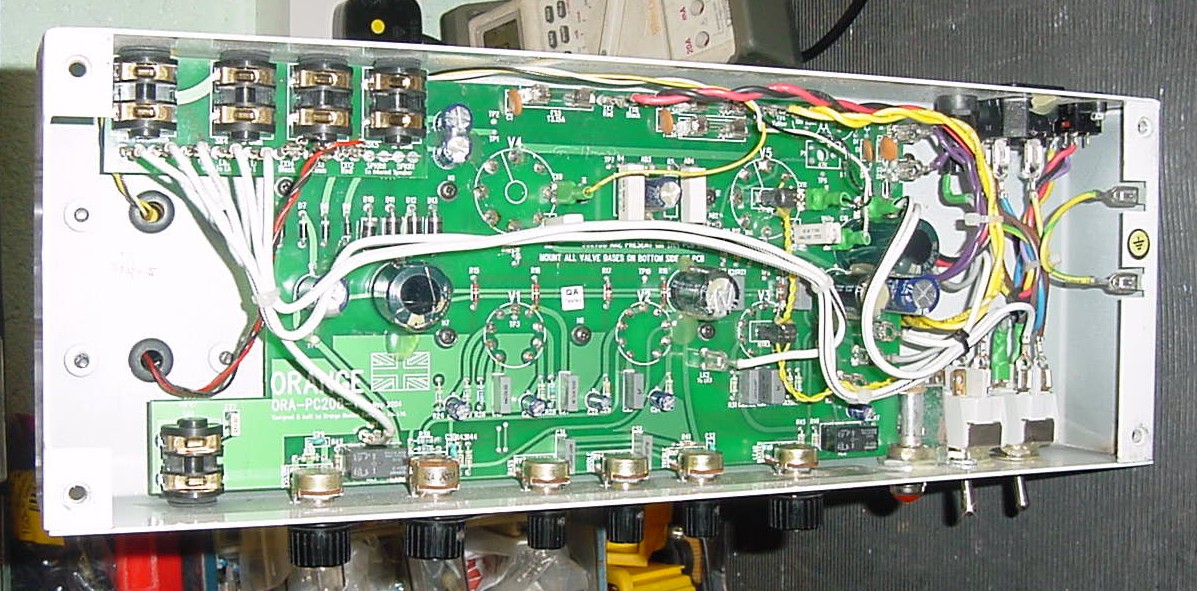
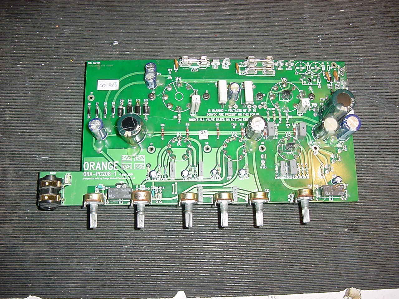
See bellow the PCB (note: the yellow/brown colour bottom right is the glare from the bench light)
Looking at the PCB The 2 bottom left hand and centre valves have DC supplied to their heaters which are wired for 6.3v mode (parallel operation), measured 4.6v DC with 2 valves connected which seems very low but I checked the 4 rectifier diodes and smoothing capacitor all ok- I would have expected about at least 5.5v however after pondering over a cup of tea - I felt the amplifier works with this low heater supply so leave alone (this is where having a schematic would be very handy).
The right hand lower valve is wired for 6.3v mode (parallel operation) but is fed from the AC heater supply
The EL34s are fed from the same 6.3v AC supply
Incidentally you can see the yellow twisted pair cable in the above picture going from the right hand EL34 to the right hand E83CC then on to the front lamp which is fed from the same 6.3v AC supply
The HT is fed from a full-wave centre-tap rectifier with capacitor filter giving 342 v DC at the anodes of the EL34s which are Pentode connected
The EL34s are cathode biased using paralleled 270 ohm resistors and 200uf capacitor so there is no bias adjustment.
G2 resistors are 1k ohm
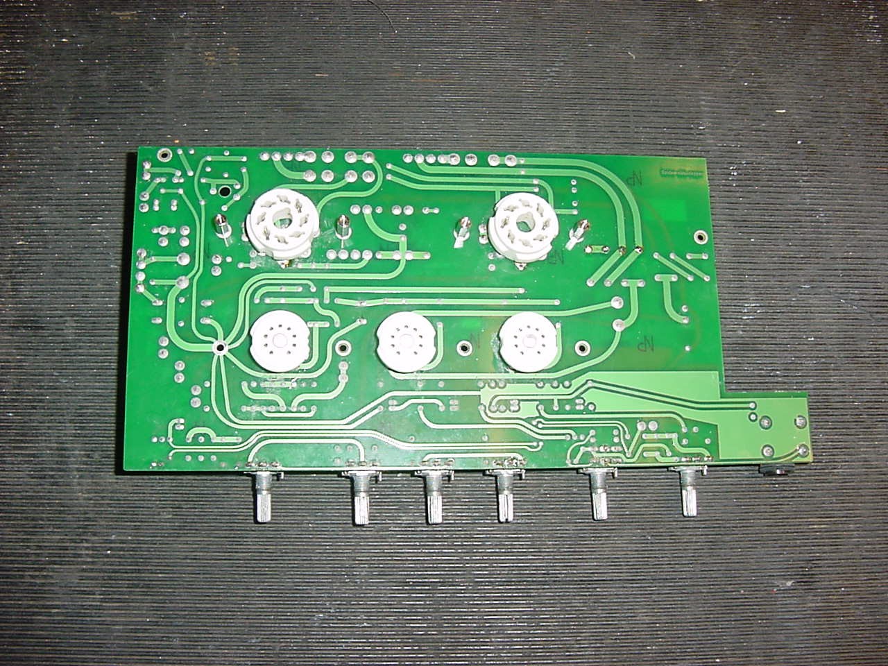
See bellow the other side of the PCB
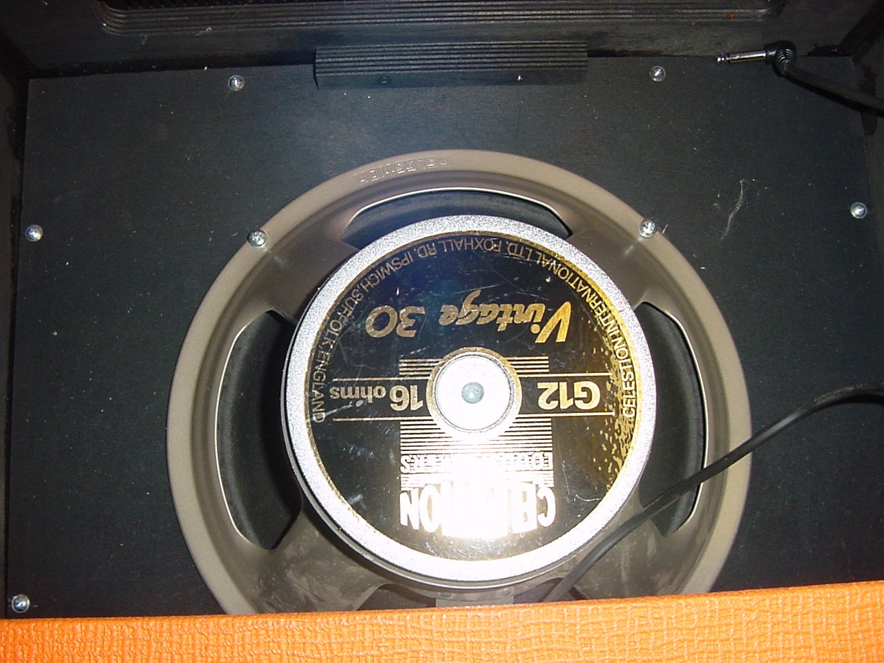
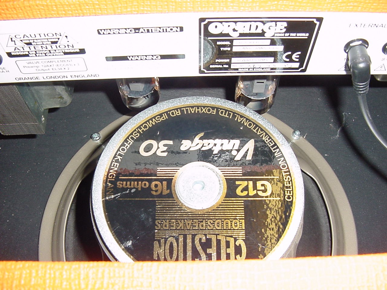
With the amplifier fully reassembled for testing it became apparent that the speaker connector was right underneath the output valves causing the speaker wire to touch the hot glass.
So to improve matters I turned the speaker round 180 degrees so the cable is completely clear of the output valves
Now much improved - fully reassembled and tested, ran the amplifier for several hours and tested at full power on the dummy load and measured 32 w RMS before clipping, also tested with the guitar all now ok
Conclusion - one of the output valves had failed causing the 500mA HT fuse to blow, replacing the valves cured the problem and the amplifier was completely checked over and is now A1. all in all a neat well built unit and MADE IN ENGLAND - you don't often say that so I have highlighted it.
We hope the above information has been of assistance to those attempting a repair, we add more examples all the time, a lot of work goes into this section of our site from the doing the repairs, photos and answering technical support emails, to keep this a free service we rely on the goodwill of people who benefit and learn from the information supplied.
Please show your appreciation, feel free to make a donation no matter how small to keep this service going.
TELEPHONE (UK)
01803- 324589
TELEPHONE (INT) +44 1803- 324589

Head Office
UNIT ONE 61 WARBRO ROAD TORQUAY DEVON TQ1 3PP BACK TO REPAIRS PAGE
©2012 A&J AUDIO. All Rights Reserved.