
REPAIR SHOP
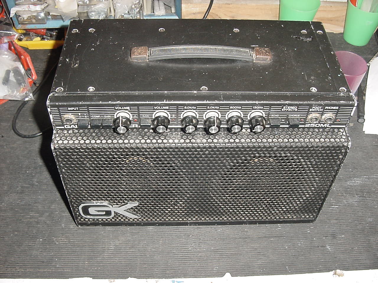
Repair of Gallien Krueger 250 ML Amplifier
Fault - Dead and blows fuses
The Amplifier had originated from the USA and had 110v Transformer fitted, the owner had run the amplifier on UK 240v mains and the unit had gone bang, he had then taken it to a technician who had fitted a new 240v transformer but had failed to revive the amplifier to working condition.
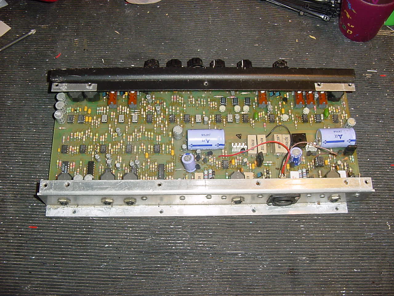
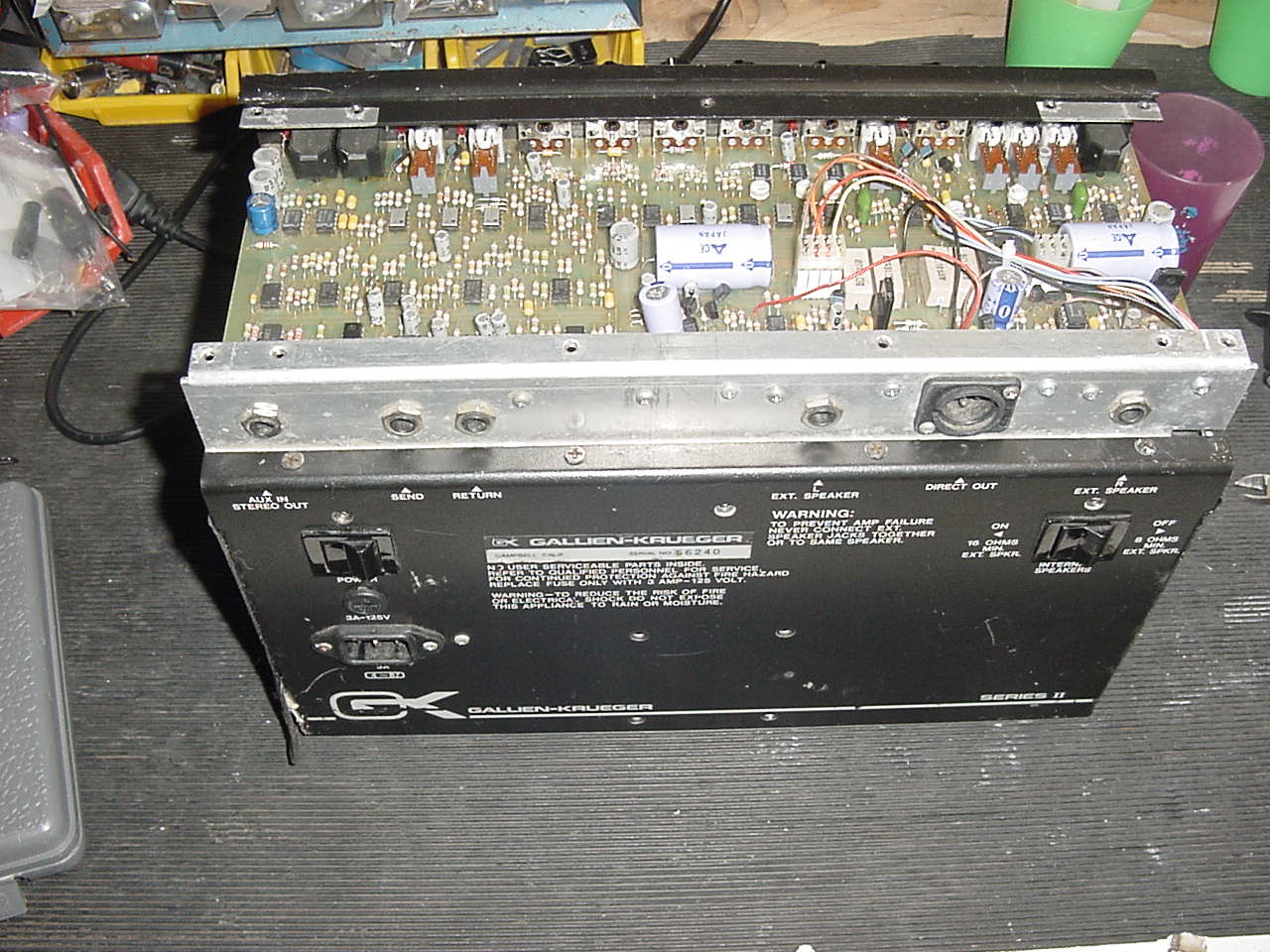
First thing was to strip the main amplifier chassis and remove for investigation as seen below.
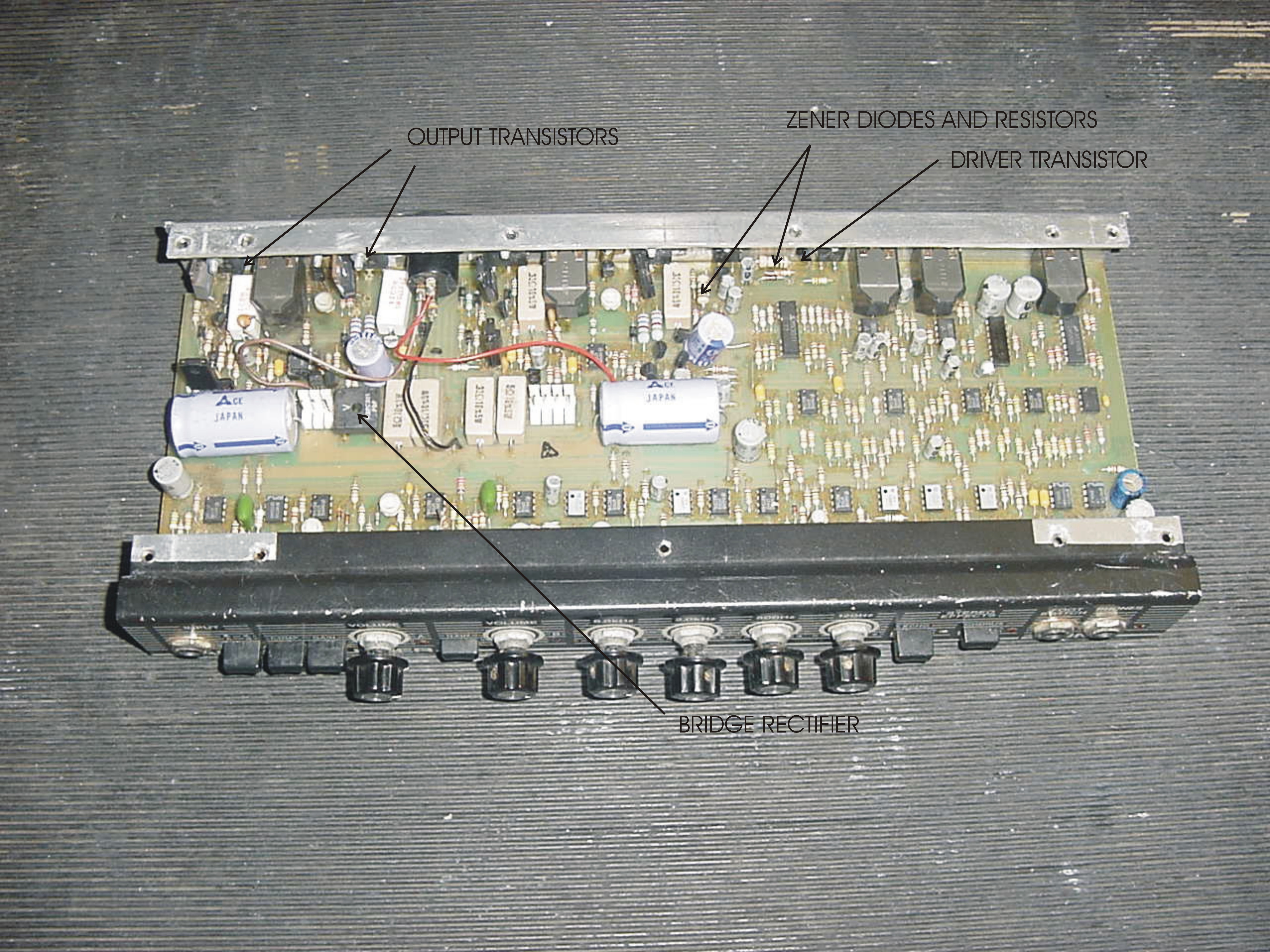
After an initial poke around with the meter found the main bridge rectifier had blown as well as 2 output transistors on one of the channels
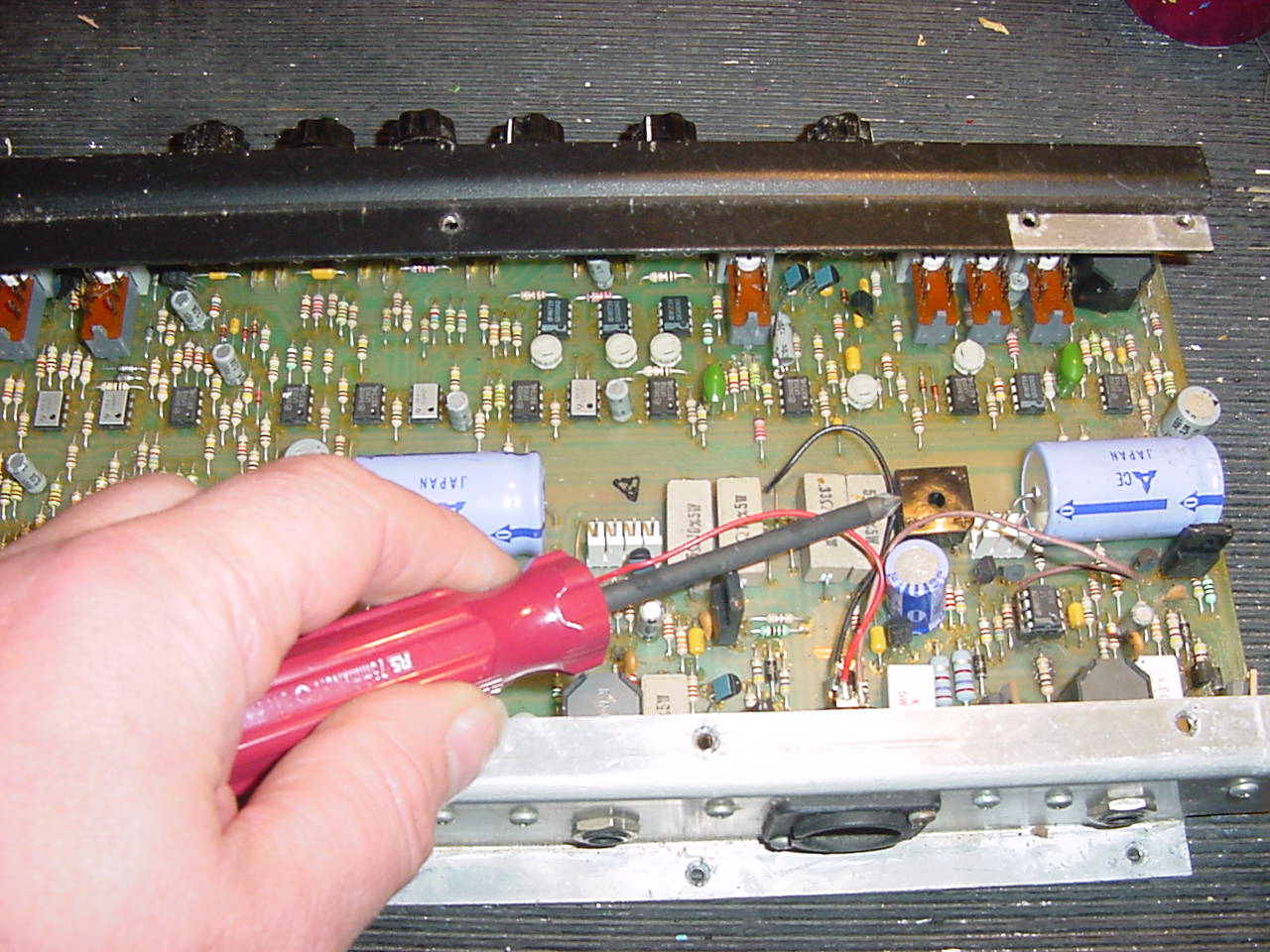
These we duly replaced and the unit powered up, the amplifier still was not working, there appeared to be no voltage on the input to the rectifier or at least not what was expected ie 30v 0 30v AC, the new bridge rectifier was still ok and the transformer had the correct voltage on its output terminals, then on a closer look realized that the secondary windings were marked 30v 0v 30v 0v and the link wire between the windings had been connected to both the 0v terminals, however as it turned out the labels were incorrect and the 30v 0v should have read 0v 30v instead so the transformer had been wired incorrectly, so re wired the transformer secondary, and hey presto 30v 0 30v AC at the bridge rectifier input, mind you the amplifier still did not work.
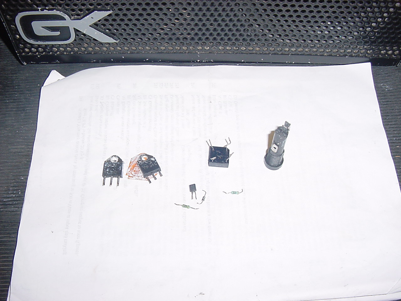
So it was time to check everything in site, the low level supply was not the correct +15v 0 -15v DC, with no + 15v found the Zener on + side was blown as was the 10 ohm resistor feeding it so replaced both Zeners and both resistors, also found and incorrect driver transistor fitted, and as it was a Japanese device the pin out configuration was different to the Motorola device it had replaced, so it would have never worked in a million years even though the transistor would have probably done the job with the base collector emitter connections correctly orientated, so removed this and fitted the correct transistor MPSA06, see below the components that were replaced.
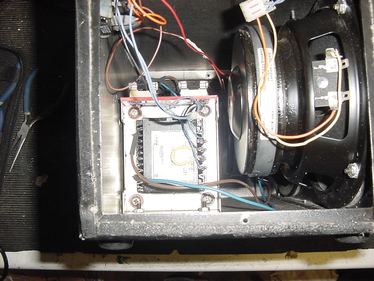
See below the amplifier assembled for testing, set the bias on each channel, all now working correctly. Also replaced the mains fuse holder and rewired the primary side of the mains transformer as this had also been incorrectly wired with switch before the fuse.
Tested unit - @ 50 RMS per channel all ok
Conclusion
This repair was like unpeeling an onion, as there were so many faults some due to the original problem of over voltage and some due to incorrectly fitted replacement parts, but in the end we got there.
We hope the above information has been of assistance to those attempting a repair, we add more examples all the time, a lot of work goes into this section of our site from the doing the repairs, photos and answering technical support emails, to keep this a free service we rely on the goodwill of people who benefit and learn from the information supplied.
Please show your appreciation, feel free to make a donation no matter how small to keep this service going.
TELEPHONE (UK)
01803- 324589
TELEPHONE (INT) +44 1803- 324589

Head Office
UNIT ONE 61 WARBRO ROAD TORQUAY DEVON TQ1 3PP BACK TO REPAIRS PAGE
©2012 A&J AUDIO. All Rights Reserved.